Awards
Indian Building Congress Award - Infrastructure Projects Cantilever Construction of Bridge over Punatsangchhu, Bhutan
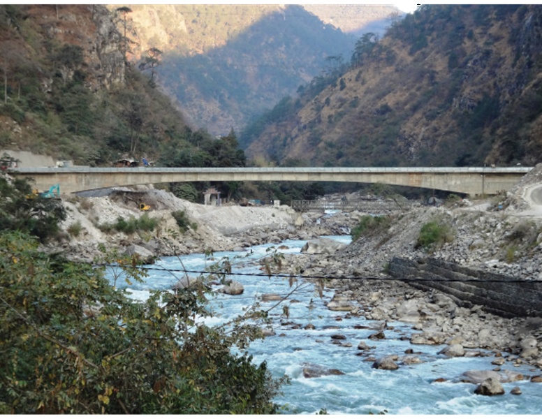
Punatsangchhu-I is the first Project of the 10,000 MW initiatives taken by the Royal Government of Bhutan (RGoB) and the Government of India (GoI) in May 2008. The Project is located on the right bank of Punatsangchhu along the Wangdue- Tsirang highway between 22 km and 35 km downstream of Wangdue Bridge. The dam site is about 94 km from Thimphu and connected by a highway.
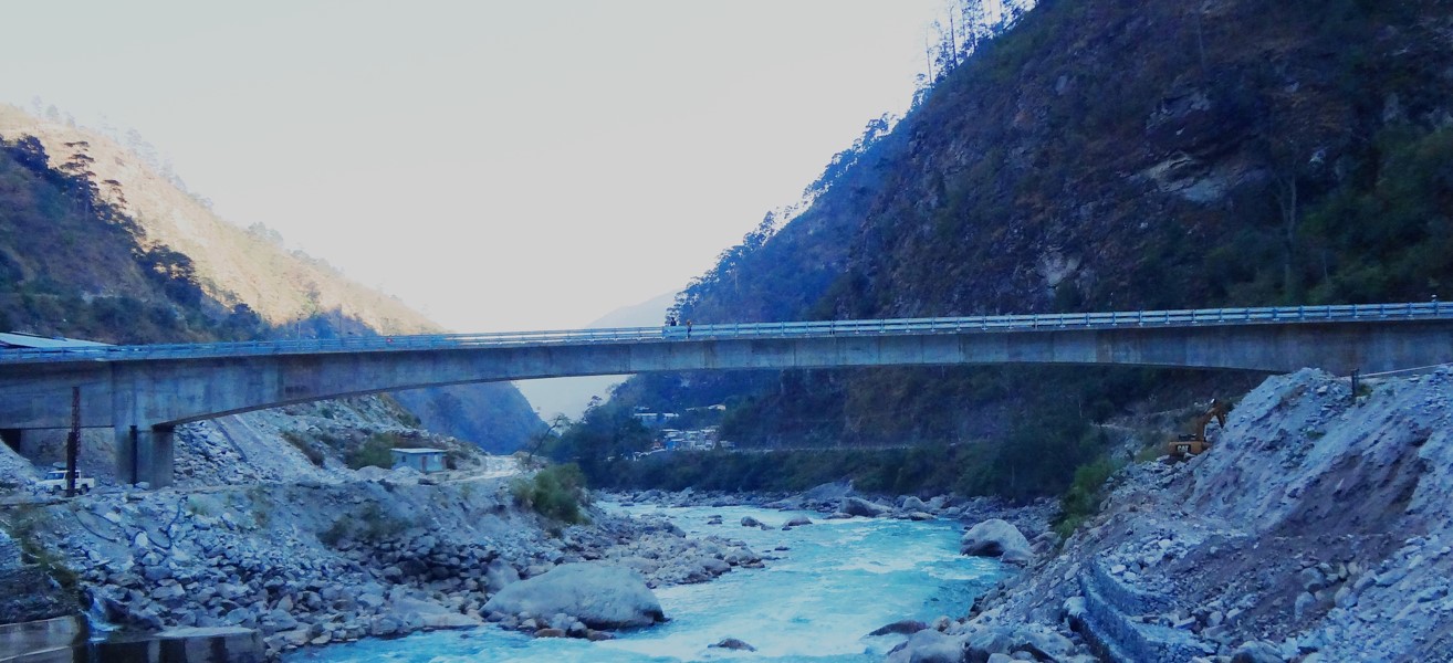
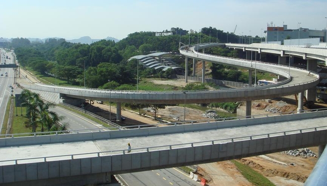
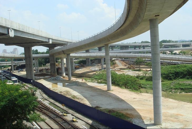
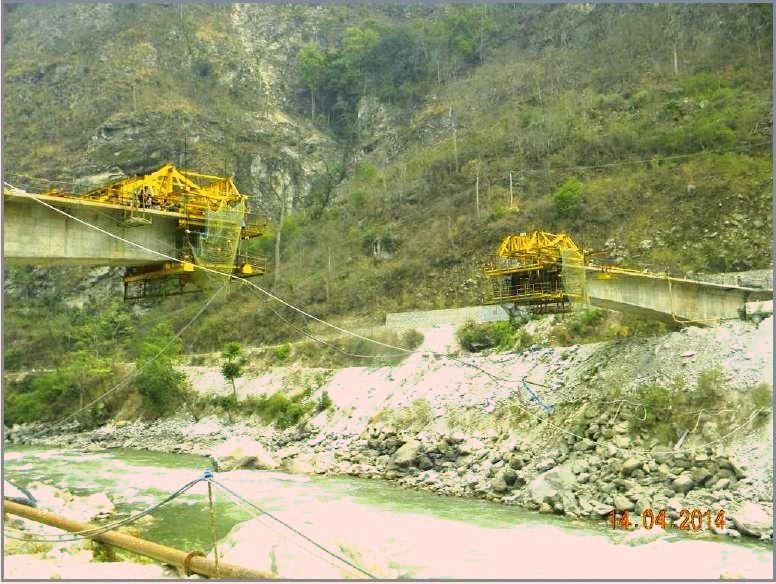
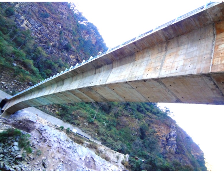
National highway and power project are on two banks of river. For transportation of heavy equipment of power project such as transformer, turbines from national highway to project site and to serve as link for staff from national highway to power plant, bridge was required to be constructed over River Punatsangchhu. The Central Span was 114m to cater to peak maximum probable flood of 1000 years for river. Space for both side spans were constrained by the presence of mountainous topography. This constrained limited end span to just 29.825m. Refer Photo 1 for site layout and Photo 2 for as-constructed bridge.
DESIGN CHALLENGES
The peculiar span configuration, construction technique, high seismic parameters and requirement for hydraulics to cater for 1000 year return period posed several design challenges as below:
1. Foundation for the Bridge was required to be designed for Peak Maximum Probable Flood in the River which corresponds to 1000 year return period. Bridge soffit level was also decided to cater for same.
2. Project was located in zone liable to shaking intensity of IX or more on Modified Mercalli Scale. This corresponds to Zone -V as per Indian Codes with peak ground acceleration of 0.36 g. This resulted in severe uplift demand on bearings at end piers during seismic transverse combination. As the end piers were short and central piers too tall, transverse moment were effectively getting locked at end piers only. To reduce this moment to manageable level, end pier was provide separate from abutment to reduce its stiffness. This resulted in sharing of transverse moments by all the piers including central piers.
3. The central piers were made integral to superstructure. To offset the effect of temperature change, creep and shrinkage due to integral structure, twin leaf slender piers were provided in place of one thick pier. This resulted in flexible piers which could absorb much of the strain without development of excessive moments.
4. Deck Width for End Spans was required to be increased to enable the turning of Long Trailors which will be used to transport Equipment for Power Project.
5. For protecting end abutment piers from hill Slopes on both sides, wing walls were required of large heights.
6. Due to short spans at ends, there was excessive uplift on end piers. Further, to ensure stability during cantilevering, checks were made for accidental case of bridge builder along with segmental disengaged with 100% increase due to impact. Additionally, density difference of 5% on both was considered in concrete of end span and central span. Construction Live load was taken as 50kg/sq.m on cantilever arm only coupled with uplifting vertical wind force on side span of 22 kg/sq.m. Weight of bridge builder was in the range of 30 T. Verification of equilibrium during construction was done for normal as well as seismic condition. Satisfying design requirement for these conditions required following design interventions:
a. Providing end span of constant depth of 6.0 m to have high counterbracing weight
b. Filling plum concrete inside the box in end span to provide counterweight of 16 t/m.
c. Central span was made monolithic to piers to enhance stability of structure as well as improve seismic performance of bridge
d. Extending diaphragm transversally to increase c/c spacing of bearings to limit uplift due to transverse moments due to earthquake
7. At end piers, bridge was transversely restrained by providing stoppers from pier cap butting against superstructure.
Awards
Indian Building Congress Award - Infrastructure Projects Cantilever Construction of Bridge over Punatsangchhu, Bhutan